 |
 02-25-2014, 10:25 AM
|
#1
|
|
Senior Member
Join Date: Jul 2013
Location: po dunk
Posts: 113
|
Magnum 3000w inverter in 50amp system
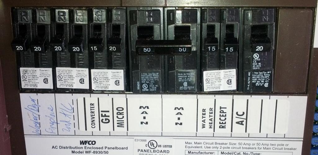
Hello, If I go the expensive route I will install a Magnum MSH-3012-M Hybrid PSW inverter/charger. I would want the ability to run the entire RV (not all at once of course) via this unit so would have to re-wire. Looking at WFCO's manual for the 8950/30 power distribution panel it looks like the right hand 50 amp breaker powers the breakers to the right of it and the left hand 50 amp breaker powers the breakers to the left of it.
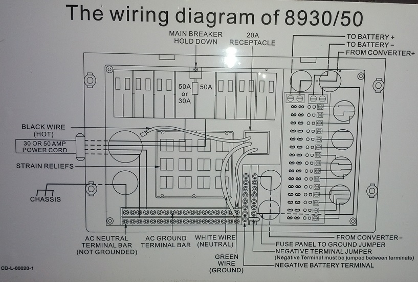
I would have to switch the GFI and water heater so all my outlets were on the right hand 50 amp breaker. Next replace the full width 20 amp breaker for the main air conditioner with a double 20 like the ones way over on the left and reconnect the Ac to one of the new 20 amp breakers and move the micro to the other. Now I would have everything I will ever use on the "red leg" and would wire it through the inverter utilizing it's built in 60 amp transfer switch. Sound about right so far?

I would have all the left hand breakers off all the time as I would not use any of that stuff. I all ready have the ac plug from my refrigerator unplugged so it can never run on ac. The magnum manual states " The AC input and output neutrals must be isolated from each other, do not route the AC input and output neutrals to a common neutral bus." When I take the red leg loose from it's 50 amp breaker and extend it to the inverter with a length of 8/2 wire I would connect the neutral of this new wire to the neutral bus in the picture and the ground to the ground bus. Now with a second new length of 8/2 I would connect from the inverters ac output with the hot (black) going to the right hand 50 amp breaker but where will the neutral go?
Jeff
|

|

|
|
02-25-2014, 10:56 AM
|
#2
|
|
Senior Member
Join Date: Jul 2013
Location: Box Elder
Posts: 2,907
|
It almost appears that you would need a double throw switch to be able tie the load side neutrals on the common position, the inverter output neutral to one switched side and the other switched side back to the normal neutral position back at the neutral bus bar in the panel. Label the switch 'Inverter' and 'Normal' or whatever would work for you and then put a reminder label on the inverter to put the switch in whatever position you are using the system.
__________________
Bob & Becky
2012 3402 Montana
2012 Chevy 2500HD D/A CC
|
|
|
|
|
04-07-2014, 08:01 AM
|
#3
|
|
Junior Member
Join Date: Apr 2014
Location: North Tustin ca
Posts: 14
|
Jeff,
I am courious how you decided to wire the Magnum Hybred.
I have just mounted the same 3012H and accomplished the DC wiring.
I need to tackle the AC side next.
Thanks
Ron
|
|
|
|
|
04-07-2014, 12:44 PM
|
#4
|
|
Senior Member
Join Date: Jul 2013
Location: po dunk
Posts: 113
|
I'm going with a household sub panel (load center) mounted in the pass through storage area. It will be right behind the WFCO power distribution center so the existing wiring for the branch circuits will reach. FYI the two position load centers will handle 4 circuits, do not have an incoming main breaker, and cost around 20 bucks. I will probably pull the double 15 amp breaker currently powering the water heater and non GFI receptacles and replace it with a single 30 amp to feed the inverter. The double 15 will go in the new sub panel along with a new double 20. I'll use 6/2 wire from the 30 amp breaker, neutral and ground bus bars to the inverter input then a second length of 6/2 from the inverter output to the sub panel bus bars. I'll move the Main air conditioner and the micro to the double 20 in the sub panel and both receptacle circuits to the double 15 in the sub panel. The water heater can go over where the GFI receptacles used to be. Then of course put a new label in the WFCO.
Show us your installed DC wiring please. I'll do plenty of pictures of my install when ever I can get to it. Pretty sure I'm done designing. Here is my plan for the DC side.

-Jeff
|
|
|
|
|
04-27-2014, 06:31 PM
|
#5
|
|
Junior Member
Join Date: May 2013
Location: Covington, WA
Posts: 10
|
Wiring for the inverter
Since you are trying to run your entire Rv on batteries, why would you want to run the ac on the inverter? If you have a generator, then run the generator and charge your batteries when you need AC. For me, the inverter is so I can get ready for the day and have my coffee (and the wife can have her hair dryer) before people around me are up and ready to hear a generator. That is also why the wiring is organized the way it is. If you plug into a 30 amp receptacle then you don't get the recept and AC on the right of the main. What I want to do is intercept the black, white and green wires from the shore and generator power and run it thru the inverter. That way everything else stays the same.
|
|
|
|
|
04-28-2014, 02:39 AM
|
#6
|
|
Senior Member
Join Date: Jul 2013
Location: po dunk
Posts: 113
|
Quote:
Originally Posted by kenhillwa

Since you are trying to run your entire Rv on batteries,
|
I'm not trying to run the entire RV on batteries.
Quote:
Originally Posted by kenhillwa
why would you want to run the ac on the inverter?
|
This is the Hybrid version of their inverter. It will take the inrush surge from the solar charged batteries then run the AC from generator when compressor is running.
-Jeff
|
|
|
|
|
04-28-2014, 03:18 AM
|
#7
|
|
Senior Member
Join Date: Jul 2013
Location: po dunk
Posts: 113
|
Quote:
Originally Posted by kenhillwa
If you plug into a 30 amp receptacle then you don't get the recept and AC on the right of the main.
|
This is incorrect. With a 50 to 30 or 50 to 15 adapter L1 (black) and L2 (red) are paralleled.
-Jeff
|
|
|
|
|
05-02-2014, 06:20 PM
|
#8
|
|
Junior Member
Join Date: Apr 2014
Location: North Tustin ca
Posts: 14
|
jeff;
I have a much bigger load center, that is only half utilized.
I am considering modifying it per your original thought.
Instead of 2 bus's, I would seperate a leg to ineffect create a 3rd buss or subpanel within the same load center.
Easy to do, and then add a 2nd common bus bar to ensure the inverted output loads are on a seperate common bus.
I see you decided to add a sub panel.
If I find that I can not make this work, I will go that route, but I am in effect adding a sub by modifying the load center. I will have to label it accordingly, but I dont see that as an issue.
I also noticed that all my heavy load items 2 ac's micro etc are on the same 50 am circuit...its not taking advantage of (or needed) the 100 amp potential.
FYI
I also have a fair battery bank and solar.
I want to power most of the panel minus the water heater and fridge.
(my rv tech friend want me to put in a residential fridge...not keen on that just yet.)
The only negative I see in my thought process is If I remove my toys and install in another rig, I may have to replace the modifyied load center or disclose that it is modifed...I will try and post the inverter location. I installed the inverter in the forward bay with the batteries. I wanted to keep the dc 4/0 wire run as short as possible, and I have non gassing agm batteries. I built a rack above my hyd slide pump assembly.
I can not tell you how many times I camp at a relatives farm or sub par camping resort where I can only draw 15 or 20 amps.
I am excited about the Hybred.
|
|
|
|
|
06-02-2014, 01:38 PM
|
#9
|
|
Junior Member
Join Date: Apr 2014
Location: North Tustin ca
Posts: 14
|
So far I really endorse the hybrid inverter.
Using magnums 50 wiring amp example
I did add a new ac main with L1, common and ground
Routed thru the inverter and back to my old panel now sub panel.
My old main ac panel is now my sub panel
Per the magnum example a new main is not required
The diagram only shows wire routing thru a junction box.
I thought a new main was the most efficient way to go
Now on my sub panel,
I have the split bus L1 and L2
L1 is from inverter which can pass thru shore power plus inverter support.
L2 is the stuff or load I don't want the inverter to try and carry in low or no power settings.
I have 450 watts of solar and 600 ah of lifeline AGM batteries.
I have found that I can run 1 of my AC units on my honda 2000,
Plus whatever else I may want.
Where the inverter covers the compressor start up amps required.
The inverter then operates in load support mode,
Using the honda output and solar where necessary with very little to no impact on the batteries.
I am enjoying the fact that I don't have run a generator for a pot of coffee or to watch the news on my sat receiver. In practice so far I have deployed the honda on my current trip to Grand Canyon etc..
Enjoying the need to not have to plug in at at this point.
Ron
|
|
|
|
|
06-02-2014, 03:13 PM
|
#10
|
|
Senior Member
Join Date: Jul 2013
Location: po dunk
Posts: 113
|
Excellent, this is precisely how I plan to use it. I like your way of running L1 through it. What are you limiting shore power draw to?
-Jeff
Sent from my Galaxy Nexus using Tapatalk
|
|
|
|
|
06-20-2014, 09:02 AM
|
#11
|
|
Member
Join Date: Jun 2014
Location: Tustin, CA
Posts: 92
|
While working on this did you happen to notice what wire gauge that Keystone used for the 50A primary feeds?
Code says that you can get away with 8 AWG 75˚C wire but I feel more comfortable with 6 AWG rather than pushing 8 AWG to the limits especially if you sitting out in the desert at 105˚F  .
|
|
|
|
|
06-20-2014, 10:28 AM
|
#12
|
|
Senior Member
Join Date: Jul 2013
Location: po dunk
Posts: 113
|
Quote:
Originally Posted by Timon
While working on this did you happen to notice what wire gauge that Keystone used for the 50A primary feeds?
Code says that you can get away with 8 AWG 75˚C wire but I feel more comfortable with 6 AWG rather than pushing 8 AWG to the limits especially if you sitting out in the desert at 105˚F . |
6 gauge 105c
Sent from my SCH-I545 using Tapatalk
|
|
|
|
|
06-20-2014, 12:10 PM
|
#13
|
|
Member
Join Date: Jun 2014
Location: Tustin, CA
Posts: 92
|
Wow, they went on the high side using not only 6 AWG wire but 105˚C as well. That's great.
Thanks for the info.
|
|
|
|
|
06-20-2014, 01:18 PM
|
#14
|
|
Senior Member
Join Date: Jul 2013
Location: po dunk
Posts: 113
|
Quote:
Originally Posted by Timon
Wow, they went on the high side using not only 6 AWG wire but 105˚C as well. That's great.
Thanks for the info.
|
Yup I couldn't believe it either had look real close and ensure that.
Sent from my SCH-I545 using Tapatalk
|
|
|
|
|
 Posting Rules
|
You may not post new threads
You may not post replies
You may not post attachments
You may not edit your posts
HTML code is Off
|
|
|
|
 » Recent Threads
 |
|
|
|
|
|
|
|
|
|
|
|
|
|
|
|
|
|
|
|
|
|
|
|
|
|
|
|
|
|
|
|
|
|


 Linear Mode

